

Categories


- Description
- Datasheet Document Download
- Guidance videos
- Reviews
- Shipping & Returns
Product Name:DC 12V 24V LED Digital Relay Switch Control Board Relay Module Voltage Detection Charging Discharge Monitor Test
Packing list : DC 12V 24V LED Digital Relay Switch Control Board Module Relay Module

Product parameters:
1. Timing range: 0~999Min
2. Working power supply: 12V Version : DC 10-16V ;24V Version : DC 20-30V
3. Voltage detection error: ±0.1V
4. Voltage detection display range: 0~99.9V
5. Electrical durability: >100,000 times (10A-250VAC)
6. Electric shock load: 10A/277VAC 10A/30 DC
7. Relay parameters: a group of conversions (normally open and normally closed points)
8. Working current: 55mA/12V when the relay is closed, standby current when the digital tube is off: 8mA/12V
9. Three-digit digital tube: It can be set to automatically turn off the digital tube (0~9Min); the set parameters can be saved for 30 years after power off
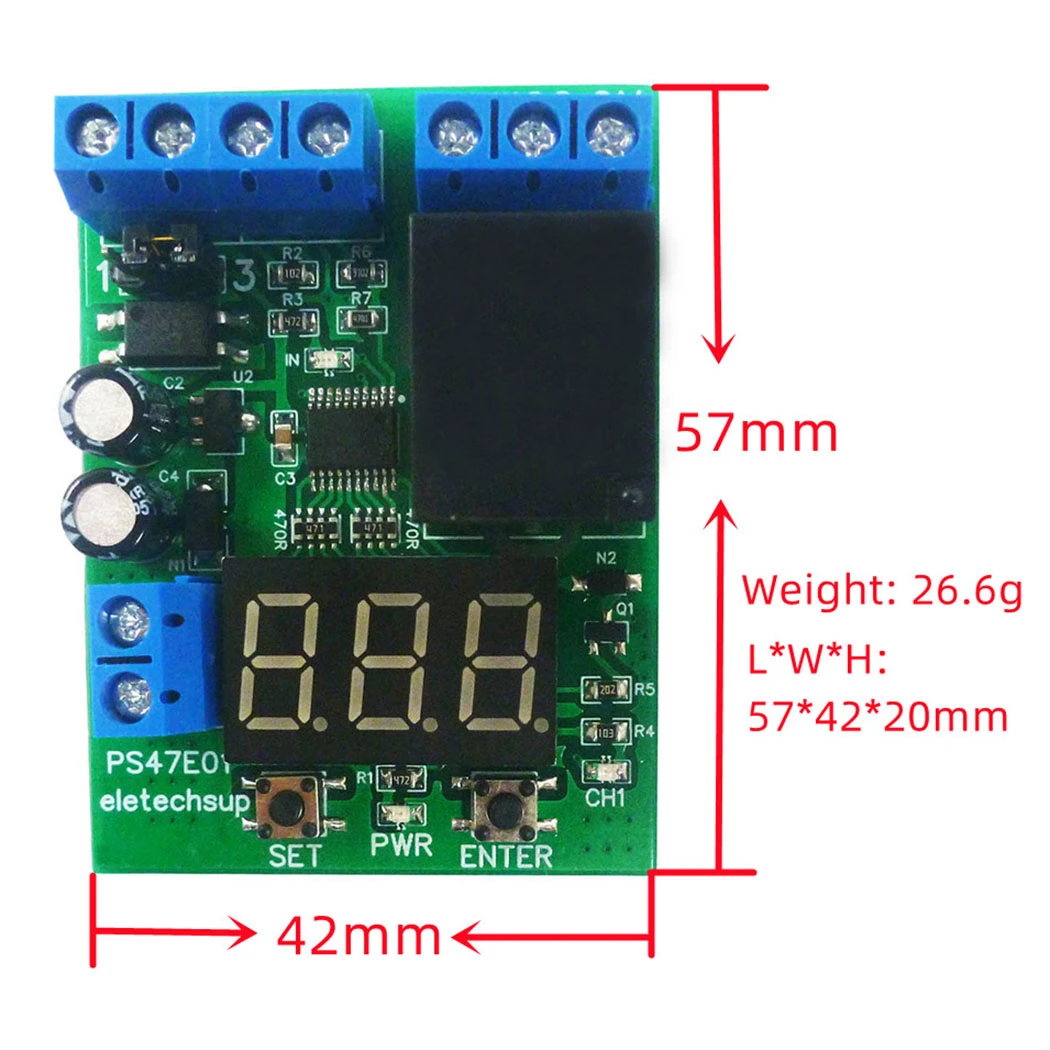
10. Weight: 26.6g
11. L*W*H: 57*42*20mm
12.Working environment temperature: -40℃~ 85℃
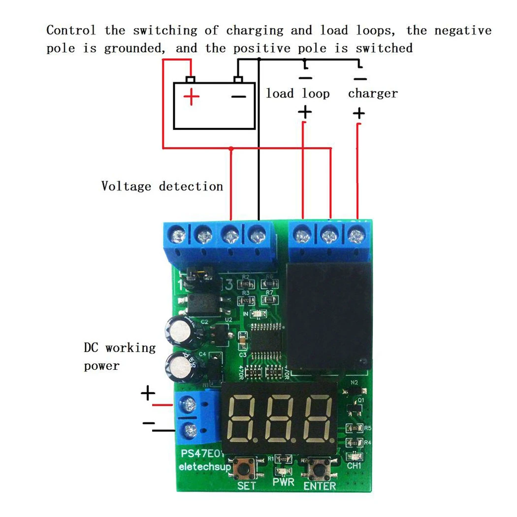
Interface Description:
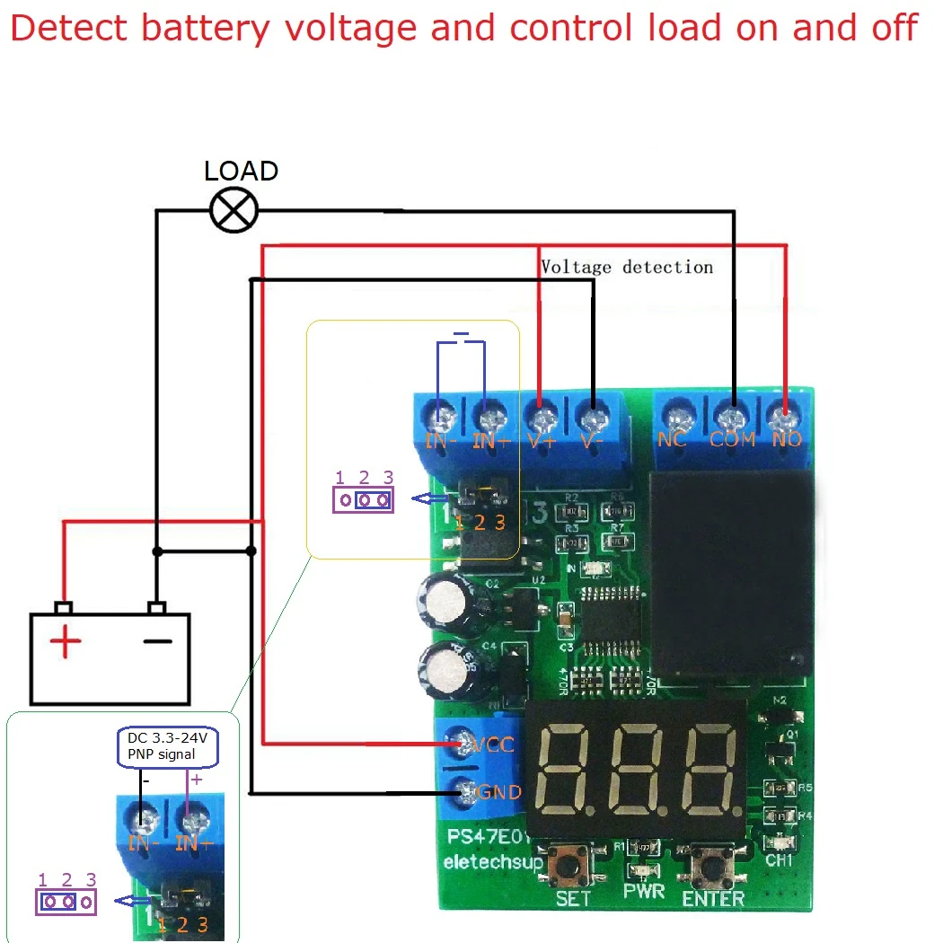
V+ : Voltage detection positive input terminal
V- : Voltage detection ground
IN+ : Forced switch signal input
IN- : Forced switch signal input
NO : The relay is normally open
COM: relay common terminal
NC : Normally closed terminal of relay

Instructions for use:

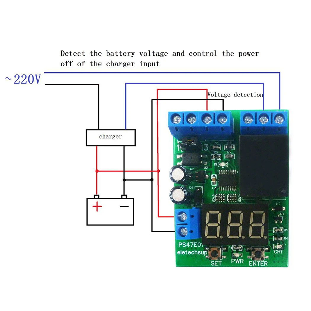
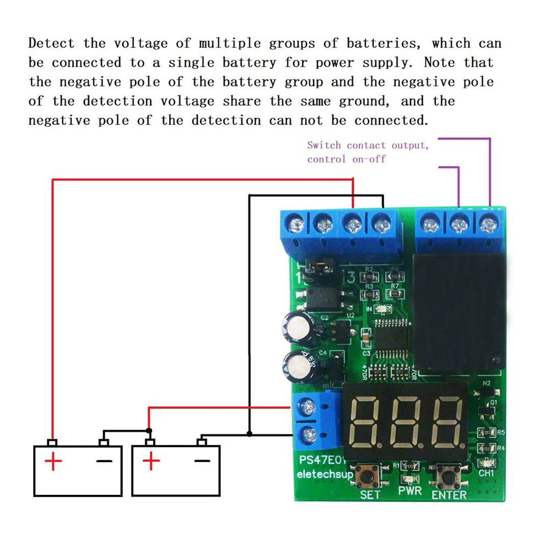
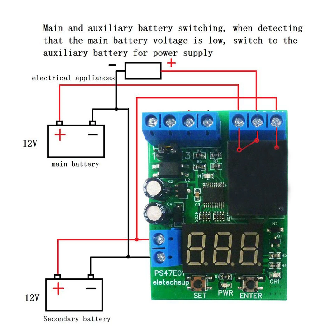
After the module is powered on, the indicator light flashes four times and then stays on, the digital tube displays the detection voltage, short press the SET key to enter the setting, the set value digit flashes, press the ENTER key to make the set value from 0 to 9 The cycle increases, the first to be set is the upper limit of the voltage, short press the SET button three times, the second group to be set is the lower limit of the voltage, the lower limit of the voltage cannot be set higher than the upper limit, (if the lower limit is The value cannot be set, please increase the upper limit first), short press the SET key to enter the third group of values for the voltage correction value, the default is 0, the setting range is -0.5 ~ +0.5, and the fourth group of values is the digital tube The time of automatic shutdown, such as ''dL0'' means that the digital tube is always on, ''dL9'' means that the digital tube is automatically turned off after 9 minutes. After pressing the SET setting, the digital tube is no longer flashing. At this time, it enters the voltage detection control mode and collects real-time data. Display the DC voltage value input from the outside, when the detected voltage is higher than the set voltage upper limit, the relay will pull in (normally open point is connected, normally closed point is disconnected), until the voltage is lower than the set voltage lower limit value , the relay is released (the normally closed point is connected, and the normally open point is disconnected).
When the voltage is detected, press and hold the SET button for three seconds and then release it, the logic state of the voltage control relay will be reversed. You can use this operation to achieve the voltage higher than the upper limit relay pull-in, or the voltage lower than the lower limit relay pull-in.
When the voltage is detected, short press the ENTER key to switch the minute timing time of the relay's pull-in status (the rightmost decimal point flashes when the timing is in progress). When the relay is released, the timing stops. Press and hold ENTER for three seconds to reset the timer value.
The forced switch can be externally connected or a voltage signal (DC5-26V) can be used to force the relay to pull in. When the external switch or voltage signal is continuously input, the relay pulls in. When the switch or signal disappears, the relay is controlled by voltage detection.
Note: The detection voltage terminals should be in reliable contact, loose wiring, and lack of insulation around the circuit board may result in inaccurate voltage detection values.
Example of wiring diagram:
* Delivery Time.
We need 1-2 days to process your order before shipping.There are two shipping methoed. Fast Delivery: The delivery time for US, European countries the delivery will take 3-5 days.Slow Delivery: The delivery time for US, European countries the delivery will take 10-15 days.
* Tracking information.
After we ship package, customer receive automatic email with tracking details.
* Lost Package Policy.
If a package did not arrive in 4 weeks after the shipping date, then this package is treated as Lost. In this case a new package will be shipped to the customer provided we are able to give the same items as those purchased by the customer. If we are not able to provide the same items to substitute the lost ones we will either propose to the customer similar items or refund their cost as it will be mutually agree with the customer. If one or more items neither the same nor similar are available to be shipped, the customer can request to cancel the order entirely, thus the total cost of the order including shipping and handling cost will be fully refunded.


