

Categories


- Description
- Datasheet Document Download
- Guidance videos
- Reviews
- Shipping & Returns
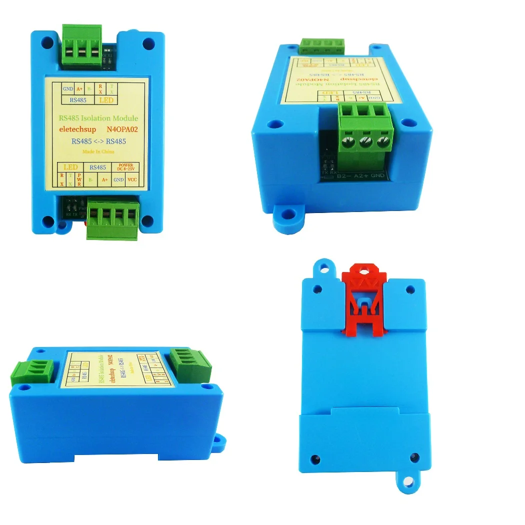
The isolated RS485 repeater is a high-performance industrial-grade RS485 signal amplifier and extender. The product can automatically sense the data flow direction and communication baud rate, without any control or handshake signals, ensuring transparent data transmission. The power supply and communication signal of the equipment are completely isolated, and measures such as surge protection and electrostatic protection are provided. It has the characteristics of long transmission distance, high speed, stable and reliable performance. Widely used in attendance machines, IC card toll systems, automatic control, access control systems, parking lots, canteen food sales systems, road toll systems.
Features
1. Industrial design, complete communication isolation, stable and reliable performance, adaptive baud rate 100-115200Kbps;
2. Built-in high-quality DC/DC isolation power module to realize electrical isolation between ports;
3. Support multi-machine communication, up to 128 nodes can be connected, and the longest transmission distance is 1500 meters;
4. Data flow automatic control technology, automatically distinguish and control the direction of data transmission;
5. Multiple protection measures: ESD protection of plus or minus 15KV, 600W dual-channel TVS protection and 2.5KV communication isolation;
6. The power supply has a wide range of 8-25VDC, and has anti-reverse connection protection;
7. Support standard 35 guide rail installation;
Electrical parameters
1 Working voltage 8-25V (DC 9V 12V 24V)
2 Working current: 12-15MA
3 3000V photoelectric isolation
4 load capacity 1-128 nodes
5 Communication distance 0-1500 meters
6 Adaptive baud rate 100-115200BPS, adaptive parity (NONE ODD EVEN)
7 Size: 100*53*32
8 Weight: 63 grams
RS485 Bus Isolation Protector
Working voltage DC 12V/24V
3000V photoelectric isolation
ESD protectio 15KV
Load capacity 1-128 nodes
Adaptive BaudRate(100-150K)
Adaptive DataBit/Parity/StopBit
Notes on RS485 Wiring
1. The RS485 communication line must use a shielded twisted pair, and it is best to use multiple strands for backup. It is recommended that the total length should not exceed 1500 meters.
2. The wiring should be kept away from high-voltage wires as far as possible, and should not be paralleled with the power wires, let alone bundled together.
3. The RS485 bus must be a hand-in-hand bus structure, and resolutely put an end to star connection and fork connection.
4. If there are more than 30 controllers or the line length is longer than 500 meters, it is recommended to use RS485 repeaters.
5. AC powered equipment and chassis must be truly grounded and well grounded.
6. Connect the GND grounds of all RS485 devices with shielded wires.
Communication using RS-485 bus wire selection requirements:
Use 2-core shielded twisted pair
Copper, wire diameter 0.5 ~ 0.75 square millimeters,
Impedance 3888 ohms/km,
Capacitive reactance 30-50 nanofarads/km,
2-core shielded twisted-pair cable with a twist distance of 20mm (if the cable distance does not exceed 500 meters, the standard of the cable can be appropriately lowered, but it must be a twisted-pair cable)
Bus limit:
It consists of two or more devices that are physically connected to each other. A maximum of 256 devices are allowed to be connected to the bus. Without repeaters, the length of the bus is not greater than 1500 meters. The system bus should not be branched. If the branch is unavoidable, the following requirements must be met:
1. The branch length should not be greater than 10 meters; the total length of the bus should not exceed 800 meters; the total number of devices on the branch line should not exceed 50.
2. All communication signal lines should be kept away from interference sources as much as possible. Signal lines should run in weak electric wells, and cannot run in parallel with strong electricity (such as 220V residential power supply) or radio frequency signal lines (such as CATV, large signal audio lines). line, the distance should be greater than 0.5 meters.
3. The joints of all lines must be connected by welding or screw clamping, and waterproof and moisture-proof treatment should be done. For example, the butt joints can be welded and tightly wrapped with waterproof tape or sealed with epoxy resin.
Signal common ground:
1. All devices on the same network segment must have a unified signal ground to avoid common-mode interference.
2. When centralized power supply, directly connect the DC negative poles of all power supplies (including the self-contained power supplies of communication equipment) on the same network segment together to form a common signal ground.
At this time, the signal ground is the DC power ground.
3. When a single household supplies power independently, connect the ground (black line) pins of all bus devices on the same network segment together to form a common signal ground.
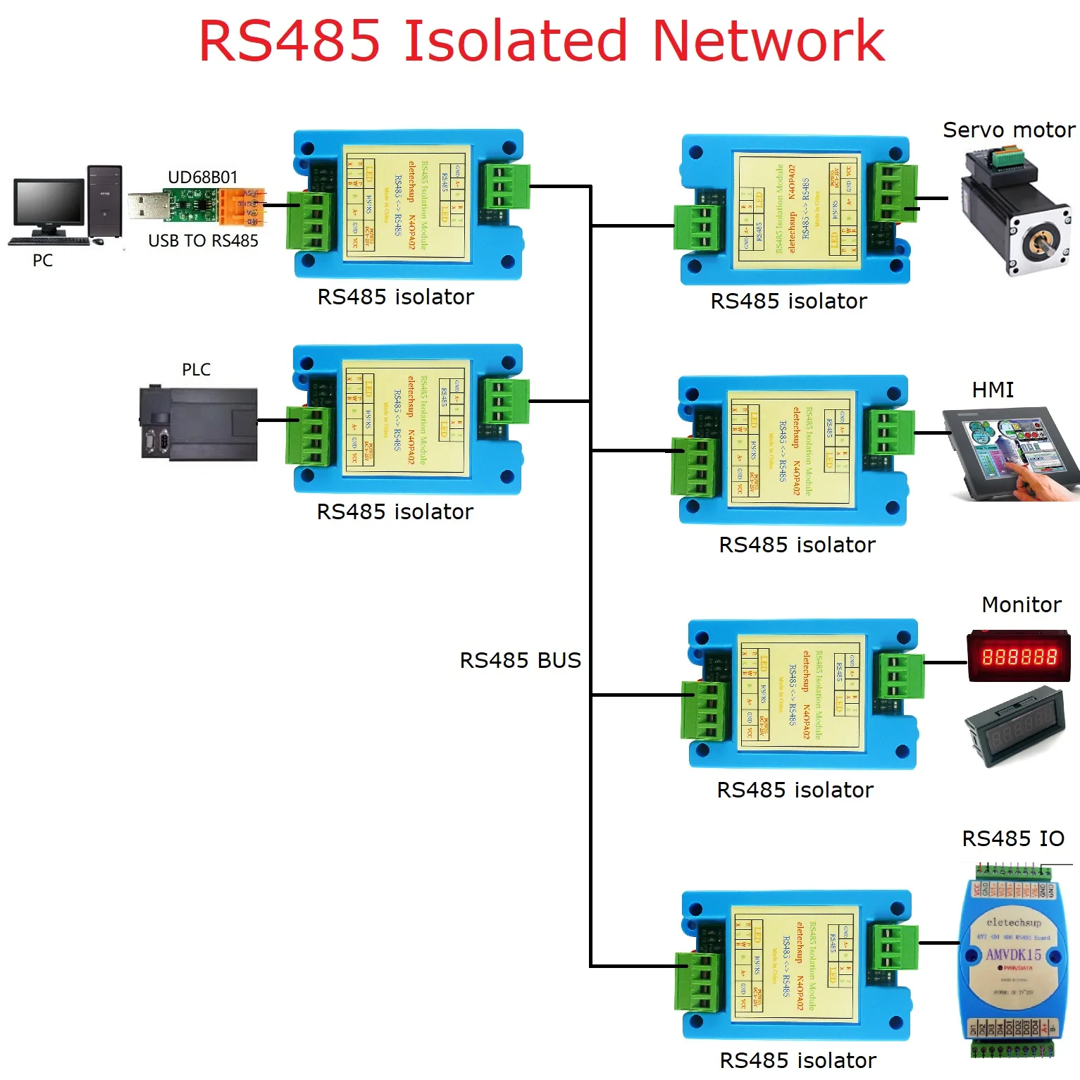
Installation and Wiring Diagram

Several debugging methods are recommended:
First of all, make sure that the equipment wiring is correct and strictly conforms to the specifications:
1. Common ground method: Use one wire or shielded wire to connect the GND grounds of all 485 devices, so as to avoid the potential difference between all devices that affects communication.
2. Middle section disconnection method: by disconnecting from the middle to check whether it is the cause of too much equipment load, too long communication distance, and the impact of damage to the entire communication line by a certain equipment.
3. Separate wire pulling method: simply and temporarily pull a wire to the device separately, which can be used to rule out whether the communication fault is caused by the wiring.
4. Replace the converter method: carry a few converters with you, so that you can rule out whether the quality of the converter affects the communication quality.
5. Laptop debugging method: first ensure that the computer notebook you carry with you is a device with normal communication, and replace the customer's computer to communicate. If it can, it indicates that the serial port of the customer's computer may be damaged.
* Delivery Time.
We need 1-2 days to process your order before shipping.There are two shipping methoed. Fast Delivery: The delivery time for US, European countries the delivery will take 3-5 days.Slow Delivery: The delivery time for US, European countries the delivery will take 10-15 days.
* Tracking information.
After we ship package, customer receive automatic email with tracking details.
* Lost Package Policy.
If a package did not arrive in 4 weeks after the shipping date, then this package is treated as Lost. In this case a new package will be shipped to the customer provided we are able to give the same items as those purchased by the customer. If we are not able to provide the same items to substitute the lost ones we will either propose to the customer similar items or refund their cost as it will be mutually agree with the customer. If one or more items neither the same nor similar are available to be shipped, the customer can request to cancel the order entirely, thus the total cost of the order including shipping and handling cost will be fully refunded.


