- Description
- Datasheet Document Download
- Guidance videos
- Reviews
- Shipping & Returns
Packname: 3 CH DC 12V 24V PWM Function Signal Generator 20Hz-1MHZ Requency Duty Cycle Square Wave Pulse Adjustable Module
1 pcs 3Ch PWM Square Wave Pulse signal Generator

Features
1 Working voltage: DC 6-24V
2 Working current: DC 12-30MA
3 3 independent buttons: used to set frequency, duty cycle, working status, etc.;Support long press, short press, simple operation and diverse functions.
4 3 Channels PWM output: PWM Signal can set frequency and duty cycle respectively.
5 PWM signal level: 5V TTL level
6 PWM signal load capacity: <20mA
7 Output frequency accuracy: 0.6% (10-30 Degrees Celsius)
8 Ultra-high frequency range: 20HZ ~ 1MHZ, duty cycle 0-100%.
9. Power-off memory function: power off at any time, the last set data will be recorded and saved when power off, and the data will be displayed when power is turned on again.
10 Automatic exit function: If there is no operation for 36 seconds, the last set data will be automatically recorded, and the dynamic setting state will be exited.
11. Real-time update function: Under the dynamic setting function, you can connect an oscilloscope to grasp the set frequency and duty cycle at any time, and output the precise frequency or duty cycle.
12. Restore production setting function: in dynamic setting mode, press and hold the UP and DOWN buttons at the same time to restore the production setting (after pressing, you need to power off and power on again, the data will be updated to the default data)
13 kinds of application scenarios: The module has a variety of control methods and working modes, and three output channels, which can meet the requirements of different environments.
14 Dimensions: 49 x 38 x 13mm
15 Weight: 14.5g
PWM signal parameter description:
1 PWM frequency: the setting range is 20HZ ~ 1MHZ. The default value is 100HZ.
Four-digit digital tube, the decimal determines the unit of frequency. When there is a decimal point, the unit is KHZ, and when there is no decimal point, the unit is HZ.
The relationship between the digital tube display number and the output frequency:
0034: Indicates that the frequency is 34HZ
0234: Indicates the frequency is 234HZ
1234: Indicates the frequency is 1234HZ
1.234 : indicates that the frequency is 1.234KHZ
12.34 : indicates that the frequency is 12.34KHZ
123.4: Indicates the frequency is 123.4KHZ
0.123: Indicates that the frequency is 0.123KHZ (that is, 123HZ)
2 PWM duty cycle: setting range 0 ~ 100
0: The corresponding PWM remains low
100: The corresponding PWM remains high
1 ~ 99: corresponding duty cycle 0.01 ~ 0.99
The relationship between the digital tube display number and the output duty cycle
0005: Indicates that the output duty cycle is 0.05/5%
0050: Indicates that the output duty cycle is 0.50/50%
Note: 1. Other combinations are also possible, but whether the data can be more accurate is related to your test tool

 How to set PWM output parameters:
Example 1:
For example, the parameters of the three channels are 100HZ/50%, 200HZ/60%, 300HZ/70%
View the parameters of the three channels:
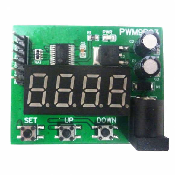
1 Powered on PWM9B03 module, the PWR indicator is on, and the digital tube is off
2 Click the SET button to display PF1 (for 1 second), and then normally display 0100 (channel 1 frequency 100HZ)
3 Click the SET button twice to display dU1 (for 1 second), and then normally display 0050 (channel 1 duty cycle 50%)
4 Click the SET button three times to display PF2 (for 1 second), and then normally display 0200 (channel 2 frequency 200HZ)
5 Click the SET button four times, display dU2 (for 1 second), and then normally display 0060 (channel 2 duty cycle 60%)
6 Click the SET button five times to display PF3 (for 1 second), and then normally display 0300 (channel 3 frequency 300HZ)
7 Click the SET button six times, display dU3 (for 1 second), and then normally display 0070 (channel 3 duty cycle 70%)
Example 2:
Set channel 1 to: frequency 1000HZ, duty cycle 40%
1 Powered on PWM9B03 module , the PWR indicator is on, and the digital tube is off
2 Press and hold the SET button for 3-5 seconds, first display PF1 (for 1 second), and then flash the number
3 Click the UP/DOWN button to adjust the number to 1000 (frequency 1000HZ)
4 Press and hold the SET button for 3-5 seconds for the second time, first display dU1 (for 1 second), and then flash the number
5 Click the UP/DOWN button to adjust the number to 0040 (40% duty cycle)
6 Re-power
Example 3:
Set channel 3 to: frequency 10.12KHZ, duty cycle 60%
1 Powered on PWM9B03 module, the PWR indicator is on, and the digital tube is off
2 Press and hold the SET button for 3-5 seconds, first display PF1 (for 1 second), and then flash the number
3 Press and hold the SET button twice for 3-5 seconds, first display dU1 (for 1 second), and then flash the number
4 Press and hold the SET button three times for 3-5 seconds, PF2 will be displayed first (for 1 second), and then the number will flash.
5 Press and hold the SET button four times for 3-5 seconds, first display dU2 (for 1 second), and then flash the number
6 Press and hold the SET button five times for 3-5 seconds, first display PF3 (for 1 second), and then flash the number
7 Click the UP/DOWN button to adjust the number to 1012, and then click the SET button to adjust the number to 10.12 (frequency 10.12KHZ)
8 Press and hold the SET button for 3-5 seconds for six times, first display dU3 (for 1 second), and then flash the number
9 Click the UP/DOWN button to adjust the number to 0060 (60% duty cycle)
10 Re-power
Example 4:
Factory Reset
1 Powered on PWM9B03 module, the PWR indicator is on, and the digital tube is off
2 Press and hold the SET button for 3-5 seconds, first display PF1 (for 1 second), and then flash the number
3 Press the UP and DOWN buttons at the same time to restore the factory settings
4 Re-power
* Delivery Time.
We need 1-2 days to process your order before shipping.There are two shipping methoed. Fast Delivery: The delivery time for US, European countries the delivery will take 3-5 days.Slow Delivery: The delivery time for US, European countries the delivery will take 10-15 days.
* Tracking information.
After we ship package, customer receive automatic email with tracking details.
* Lost Package Policy.
If a package did not arrive in 4 weeks after the shipping date, then this package is treated as Lost. In this case a new package will be shipped to the customer provided we are able to give the same items as those purchased by the customer. If we are not able to provide the same items to substitute the lost ones we will either propose to the customer similar items or refund their cost as it will be mutually agree with the customer. If one or more items neither the same nor similar are available to be shipped, the customer can request to cancel the order entirely, thus the total cost of the order including shipping and handling cost will be fully refunded.


