

Categories


- Description
- Datasheet Document Download
- Guidance videos
- Reviews
- Shipping & Returns
Package inlcuded:
1PCS DC 12V/24V 12CH DIN35 Rail RS485/Ethernet Modbus RTU Relay Board
Features:
1: DC 12V (12V Version), DC 24V (24V Version)
2: Standby current (all relays closed) 14MA, 1 relay open 41MA, 2 relays open 69MA, 3 relays open 95MA,4 relays open 122MA,5 relays open 149MA,6 relays open 174MA, 7 relays open 198MA,8 relays open 226MA
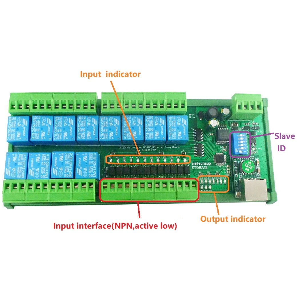
3 12 photoelectric isolation Input ports (NPN low level active ), the input and output relationship can be set to associated (default) and non-associated through commands.
4: ''open'' ''close'' ''Momentary'' ''Self-locking'' ''Interlock'' ''Delay'' ''''Interlock between two channels'' 7 Commands
5: MODBUS RTU command, Support 03 06 16 function code
6: Under the ''Delay'' command ,the maximum delay is 255 seconds;
7 :MODBUS commands can be made serial HyperTerminal (serial assistant) OR ''Modbus Poll'' Enter;
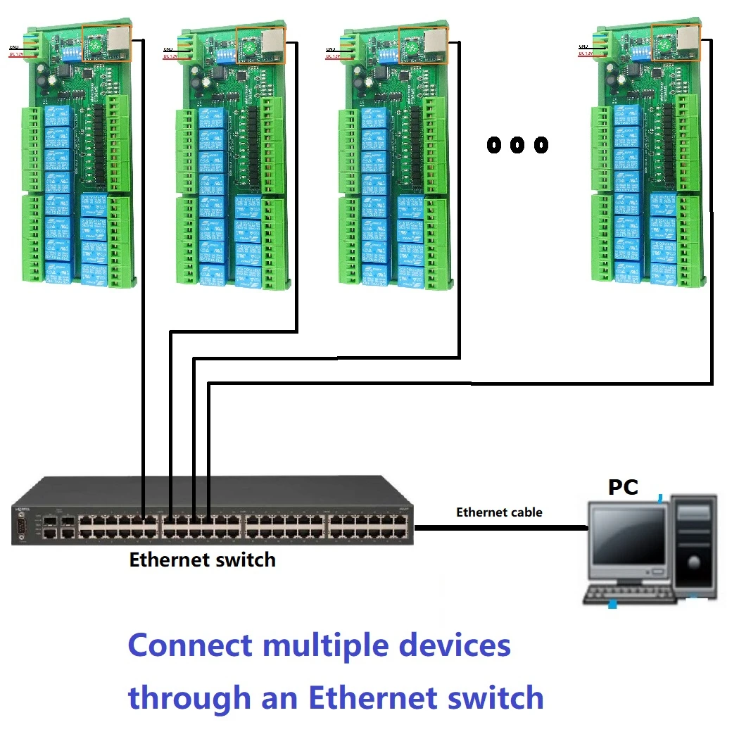
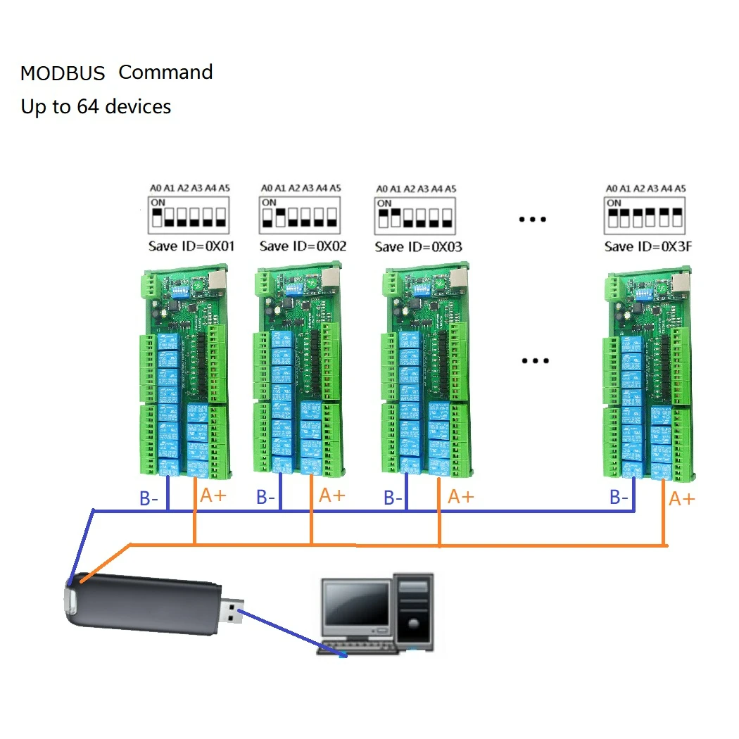
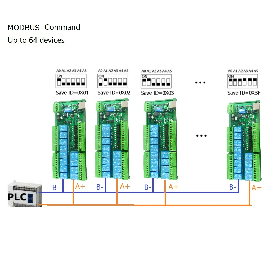
8 :Under the MODBUS command mode, it can support up to 64 devices in parallel
9 :The default baud rate is 9600BPS. The baud rate can be set by command: 2400 4800 9600 19200 38400 57600 115200BPS
10: The check methods can be none parity check, even parity check and odd parity check
11 :The data sending and returning time can be set, with a maximum value of 1000ms
12 :Size: 200 * 72 * 22mm(Only PCB Board);220 * 88* 46mm(with Din Rail Box)
13: Weight: 250.5g(Only PCB Board);382g(with Din Rail Box)
14: Maximum load: 10A / 250VAC, 10A / 125VAC, 10A / 30VDC, 10A / 28VDC, 10A / 12VDC
DIN rail Box parameters:
Product model: UM72
Color: green
Width: suitable for PCB board width UM72(72mm)
Insulation grade: flame-retardant VO grade
Backplane length: suitable for 200 mm PCB boards
Net weight:128g
Installation: DIN35 and C45 rail
Glossary:
NO : Relay normally open contact
COM : Relay common contact
NC : Relay normally closed contact
Open : NO connection COM, NC disconnect COM
Close : NO disconnect COM, NC connection COM
Momentary : Enter the Momentary command, the Rreceiver Relay is Open, delay of 0.5 seconds after, Relay is Close;
Toggle : Enter the Toggle command, the Rreceiver Relay is Open, Enter the Toggle command again, Relay is Close;
Latched : Enter the Channel 1 Latched command, the receiver Channel 1 is Open, the Channel 2 is Close.
Enter the Channel 2 Latched command the receiver Channel 2 is Open, the Channel 1 is Close.
Enter the Channel 3 Latched command the receiver Channel 1 is Close, the Channel 2 is Close.
Delay : Enter the Delay command, the Rreceiver Relay is Open, delay of 0-9999 seconds(MODBUS command is 0-255 seconds )after, Relay is Close;
During the delay, Eter the Close command, immediately close the relay
Interlock between two channels: refers to the interlock between 1-2, 3-4, 5-6, 7-8, 9-10, 11-12 channels. Input channel 1 interlock command, channel 1 relay ''open'', channel 2 relay off; press input channel 2 interlock, channel 2 relay ''open'', channel 1 ''close''; input channel 3 interlock command, channel 3 relay ''Open'', channel 4 channel relay is closed; press input channel 4 to interlock, channel 4 relay ''open'', channel 3 ''close''; and so on
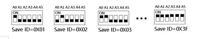
Slave ID: A0-A5 is the slave ID, you can choose 64 different slave ID.
Under the MODBUS command mode,the slave ID must be correct
command Description, Please refer to '' ETD8A12 12-channel RS485 IO input and output controller commamd''
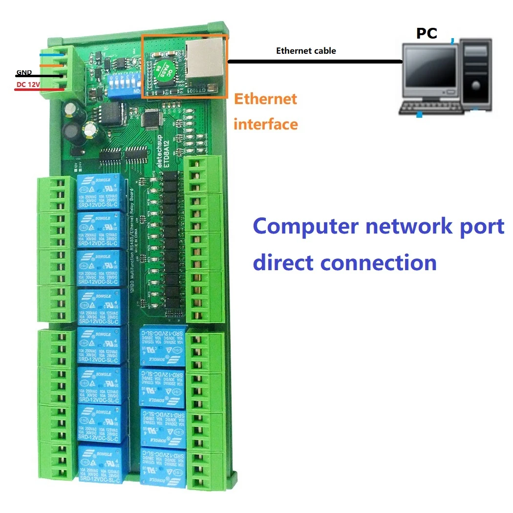
1 The dial switch (slave address) is invalid and can only control one module at a time.
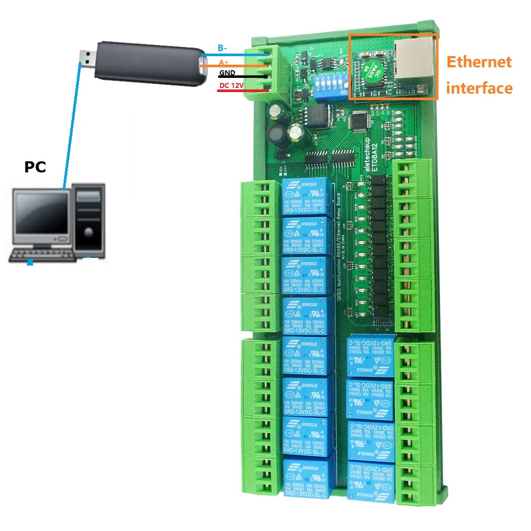
2.MODBUS command mode (HEX), you can control a variety of ways: Serial Hyper Terminal Control (need to manually add the CRC), Modbus Poll software control (software automatically add the CRC), PLC or MCU process control
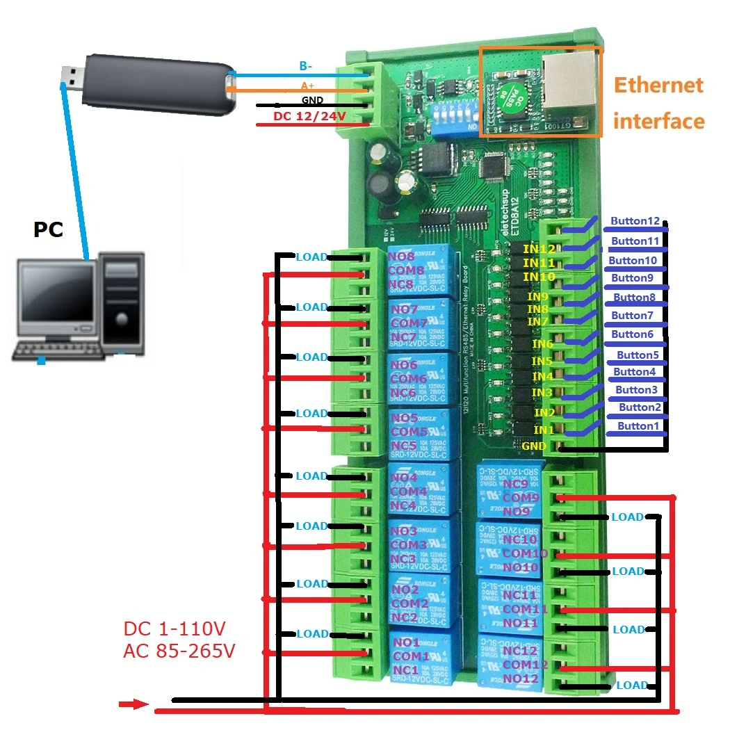
Wiring Diagram:
1 DC 12V control circuit,Wiring diagram below. ''LOAD'' may be camera,LED lights, fans, motors and other DC 12V equipment
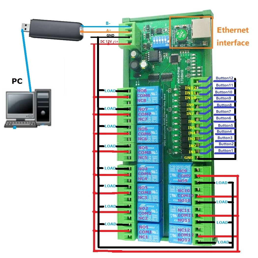
2 DC 1-110VAC 85-265V control circuit,Wiring diagram below(Note:If not DC 12V load, need another DC 12V power supply). ''LOAD'' may be LED lights, fans, motors Lights, fluorescent lights, solar water heaters and other DC AC equipment
* Delivery Time.
We need 1-2 days to process your order before shipping.There are two shipping methoed. Fast Delivery: The delivery time for US, European countries the delivery will take 3-5 days.Slow Delivery: The delivery time for US, European countries the delivery will take 10-15 days.
* Tracking information.
After we ship package, customer receive automatic email with tracking details.
* Lost Package Policy.
If a package did not arrive in 4 weeks after the shipping date, then this package is treated as Lost. In this case a new package will be shipped to the customer provided we are able to give the same items as those purchased by the customer. If we are not able to provide the same items to substitute the lost ones we will either propose to the customer similar items or refund their cost as it will be mutually agree with the customer. If one or more items neither the same nor similar are available to be shipped, the customer can request to cancel the order entirely, thus the total cost of the order including shipping and handling cost will be fully refunded.


