

Categories


- Description
- Datasheet Document Download
- Guidance videos
- Reviews
- Shipping & Returns
Product Name:0-3A 42/57/86 Stepper Motor Forward Reverse Controller PWM Pulse Speed Drive Module For Screw Slider 3D Printer Accessories
Package included:
1 PCS Drive control combination module
OR 1 PCS Stepper motor controller
OR 1 PCS Driver module
Description:
Supply Voltage : DC10V~30V
Drive Current Range:Within 3A
Controller Type:Uniaxial stepping motor controller
Signal Support:No trigger/NPN (normally open type)
Regulate Way:Ending potentiometer adjustment
Applicable Motor:Within 3A Two-phase step-in motor
Above 3A requires an external drive
Delay Range:0~999.9s
Applicable Drive:Compatible with 99% of the step / servo motor drives on the market
Velocity Range0.1~999.9 Rpm
Impulse Range:1~99990 single pulses
Drive control combination module Weight:170.7g
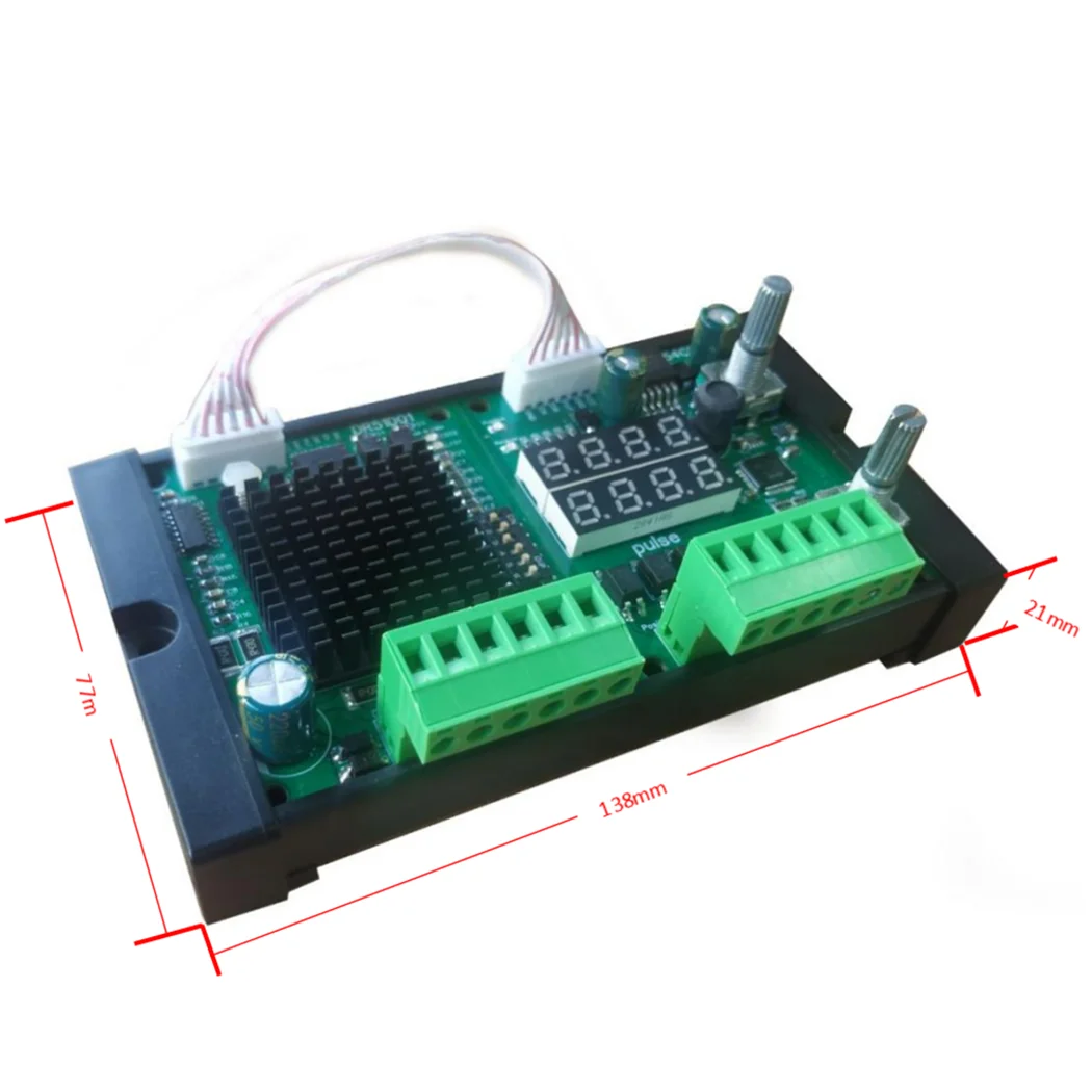
Drive control combination module Size:138*77*21mm
Stepper motor controller Weight:45.9g
Stepper motor controller Size:71*60*29mm
Driver module Weight:41.5g
Driver module Size:71*60*24mm
(NOTE:The controller does not currently support programmable PLC)
Note:Please use the switch power supply to power the drive. The power (voltage * current) is too small and it will affect the torque of the motor. The 24V5A or 12V10A universal switch power supply is recommended
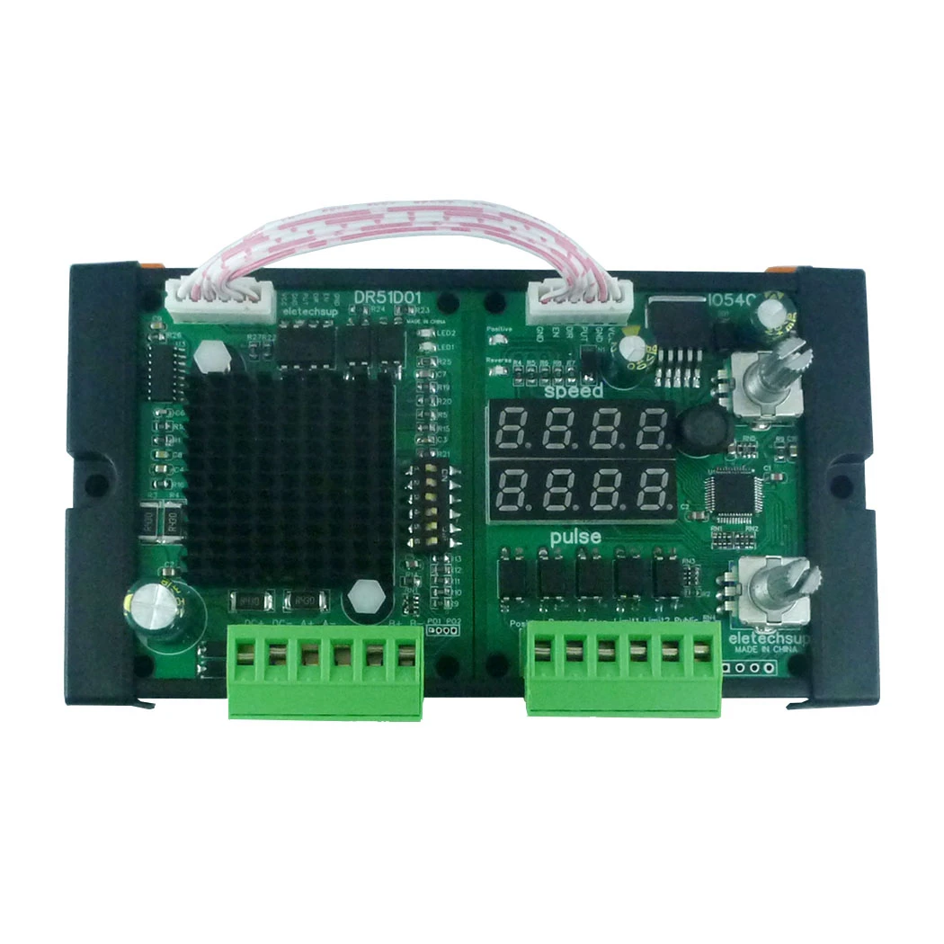
Product size chart:
During the function setting mode, turn the potentiometer No. ② to adjust the intermittent time value of the motor forward and reverse rotation
After setting the function mode, turn the potentiometer No. ① to adjust the motor rotation speed.
★Turn the potentiometer No. ② to adjust the number of pulses: for example, under the condition of 8 subdivision, 1600 pulses are a circle, press one
The lower angle adjustment potentiometer has a decimal point of 160.0 representing 16000 pulses, which is 10 turns.
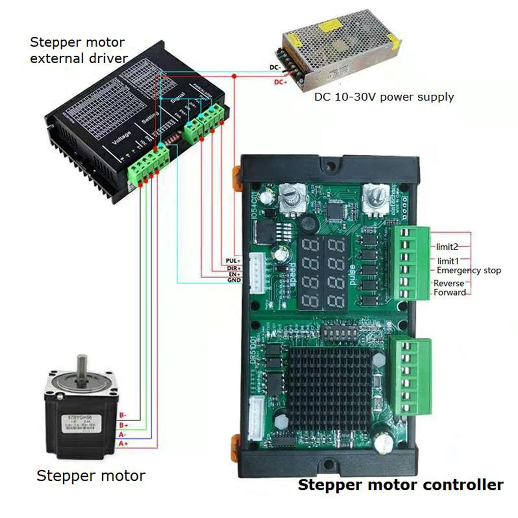
External drive link mode:
Controller EN Connect Drive EN +
Controller DIR connect to drive DR +
Controller PUL Connect drive PUL +
The controller GND drives DIR-with EN-with PUL-making their negative poles
|
Step Angle: Turn the turning angle of the stepping motor. |
|
Guide: one nut distance moved by the stepping motor. |
|
Subdivision: adjust the step angle of stepping motor. |
|
Formula: Step motor 1.8 requires 200 pulses. |
|
Example: when the stepping motor sets 1.8 step angle / 32 subdivision / 8mm guide range, it takes 6,400 pulses to run a circle of 360, and 12,800 pulses when the motor turns 16mm. |
If the speed is very low, large segmentation should be chosen to ensure smooth, and reduce vibration and noise.
Function Introduction:
|
★P-1:Point motion function Press and hold, turn, and stop with the limit or release. |
|
★P-2:Self-locking function Press positive turn to keep positive turn, press reverse to keep reverse, release constantly touch the limit stop |
|
★P-3:Give the positive signal, the motor is turning, the next positive signal, the motor reverses. |
|
★P-4:Give the positive signal,Encounter limit 1 stop T seconds after automatically reverse to limit 2 stop. |
|
★P-5:The electricity is turning,Encounter limit 1 stop T seconds→Automatic reverse to limit 2 stop T seconds→Automatic positive turn→reverse infinite loop!(General: The motor circulates back and forth between A and B, controlled by the limit) |
|
★P-6:Give forward signal, forward X angle to stop, and reverse signal to reverse X angle to stop. |
|
★P-7:Give the signal of forward rotation, stop by X angle of forward rotation, delay for tincture seconds, and stop by X angle of reverse rotation automatically. |
|
★P-8: Power-on forward rotation X angle stop, delay T seconds → reverse X angle stop, delay T seconds → forward rotation X angle stop. Infinite loop! |
|
★P-9: Give forward signal, stop forward X angle, delay T seconds → Stop forward X angle, infinite loop! Give reverse signal, reverse X angle stop, delay T seconds → reverse X angle stop, endless loop! |
Other Instructions
|
1:About motor:As long as it is a 2-phase 4-wire 5-wire 6-wire 8-wire stepper motor, the current can be controlled within 4A. |
|
2:Can I replace my own drive: It can be replaced as long as there is a similar interface |
|
3:With or without self-locking: all possible; our default delivery is with self-locking function; if self-locking is required; just remove one of the EN+ wires of our controller and leave it unconnected. |
|
4:Regarding the setting of subdivision and current size: our default setting is 8 subdivision; that is, 1600 pulses per circle; the current setting is 0.5A; if it is generally available, try not to adjust it. |
|
Step resolution select function |
|||
|
S1 |
S2 |
S3 |
Function |
|
ON |
ON |
ON |
Standby mode (the OSCM is disabled and the output stage isset to 'OFF'status) |
|
ON |
ON |
OFF |
Full step resolution |
|
ON |
OFF |
ON |
Half step resolution(Type A) |
|
ON |
OFF |
OFF |
Quarter step resolution |
|
OFF |
ON |
ON |
Halfstepresolution(TypeB) |
|
OFF |
ON |
OFF |
1/8stepresolution |
|
OFF |
OFF |
ON |
1/16stepresolution |
|
OFF |
OFF |
OFF |
1/32stepresolution |
|
Current setting |
|||
|
S4 |
S5 |
S6 |
Current value |
|
ON |
ON |
ON |
0.5A |
|
ON |
OFF |
ON |
1A |
|
ON |
ON |
OFF |
1.5A |
|
ON |
OFF |
OFF |
2A |
|
OFF |
ON |
ON |
2.5A |
|
OFF |
OFF |
ON |
3A |
|
OFF |
ON |
OFF |
3.5A |
|
OFF |
OFF |
OFF |
4A |
Common problems and strategies
|
Phenomenon |
Possible problem |
Solution |
|
The Motor does not turn |
The power light does not light up |
Check the power supply circuit, normal power supply |
|
The motor shaft is powerful |
The motor shaft is powerful |
|
|
Subdivision is too small |
Select the right subdivision |
|
|
Is the current set too small |
Select the right current |
|
|
The drive is protected |
On the electricity again |
|
|
The enabling signal is low |
This signal is high or disconnected |
|
|
Do not respond to the control signal |
Not on the electricity |
|
|
Wrong direction of motor |
Wrong connection of motor wire |
Arbitrarily swap the two wires of the same phase of the motor (for example, A+, A- swap wiring positions) |
|
There is an open circuit in the motor wire |
Check and connect |
|
|
The alarm indicator is on |
The motor wire is connected wrong |
Check the wiring |
|
Voltage is too high or too low |
Check the power supply |
|
|
Motor or drive is damaged |
Replace the motor or the drive |
|
|
Location is not allowed |
The signal is disturbed |
Suppress interference |
|
The shielding ground is not connected or unconnected |
Reliable grounding |
|
|
There is an open circuit in the motor wire |
Check and connect |
|
|
Subdivision error |
Set the right subdivision |
|
|
Current is small |
Increase current |
|
|
Stall when the motor is accelerating |
Acceleration time is too short |
Increased acceleration time |
|
Motor torque is too small |
Select high torque motor |
|
|
The voltage is too low or the current is too small |
Increase voltage or current appropriately |
* Delivery Time.
We need 1-2 days to process your order before shipping.There are two shipping methoed. Fast Delivery: The delivery time for US, European countries the delivery will take 3-5 days.Slow Delivery: The delivery time for US, European countries the delivery will take 10-15 days.
* Tracking information.
After we ship package, customer receive automatic email with tracking details.
* Lost Package Policy.
If a package did not arrive in 4 weeks after the shipping date, then this package is treated as Lost. In this case a new package will be shipped to the customer provided we are able to give the same items as those purchased by the customer. If we are not able to provide the same items to substitute the lost ones we will either propose to the customer similar items or refund their cost as it will be mutually agree with the customer. If one or more items neither the same nor similar are available to be shipped, the customer can request to cancel the order entirely, thus the total cost of the order including shipping and handling cost will be fully refunded.


