

Categories


- Description
- Datasheet Document Download
- Guidance videos
- Reviews
- Shipping & Returns
Product Name: 4ch DC 5V 12V 24V DIP Switch Delay Relay Module Flip-Flop Latch Bistable Self-locking Interlock Latch Power Conditioner
Package inlcuded:
1 PCS IO26G04 DC 5V/12V/24V 4ch Dip Switch relay module
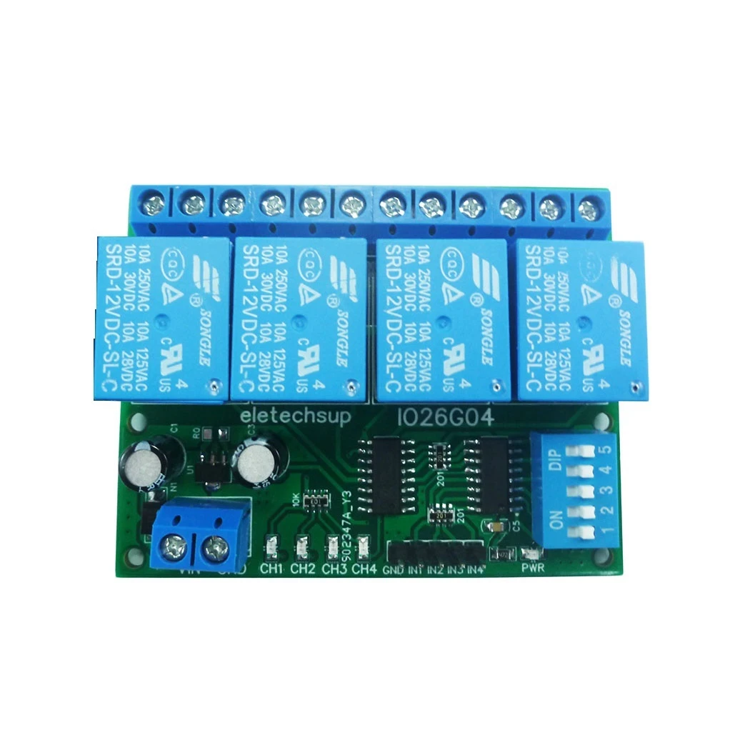
Product Specifications:
1 Operating voltage: DC 12V(DC 5V/ 24V Optional)
2 Operating Current(DC 12V) : Standby current 4MA, 1 relay open 32MA, 2 relays open 59MA, 3 relays open 86MA, 4 relays open 114MA;
3 Size: 68 x 53.5 x 20 mm
4 Weight : 58g
5 Relay maximum load capacity: DC 1-110V/5A; AC 85-265V/6A
Product Features:
4 channel relay, each channel independently triggered independent delay, do not interfere with each other.
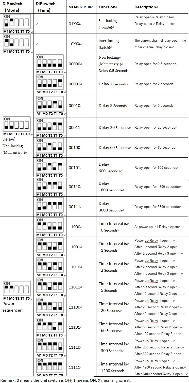
4 kinds of Functional mode: Delay/ Non-locking (Momentary ); Self-locking (Toggle); Inter-locking (Latch); Power sequencer(Relay sequence opens)
Low pulse trigger(Connect to the power supply GND via the trigger button or low level control via the MCU IO port)
The function mode and delay time are selected by the DIP switch.
Noun resolved:
NO : Relay normally open contact
COM : Relay common contact
NC : Relay normally closed contact
Relay open: COM connect NO.
Relay close: COM disconnect NO.
Typical applications:
Automotive electronics
AC DC Motor
Audio amplifier Sequential power up.
Power Conditioner/Sequencer
LED
Smart Home
Emergency lighting
MCU development board
Toy car
UNO MEGA2560
Car delay power off function
how to use:
Select the desired function mode and delay time via the DIP switch on the board.
Note: Re-power up after changing the Dip switch
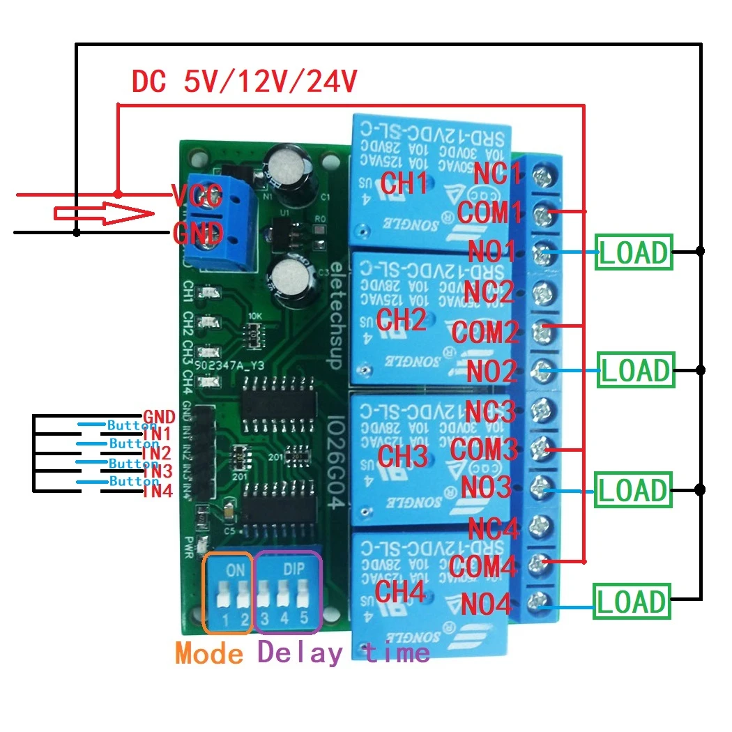
Wiring diagram:
1 DC 12V Control circuit,Wiring diagram below. ''LOAD'' may be LED lights, fans, toy car and
other DC 12V equipment
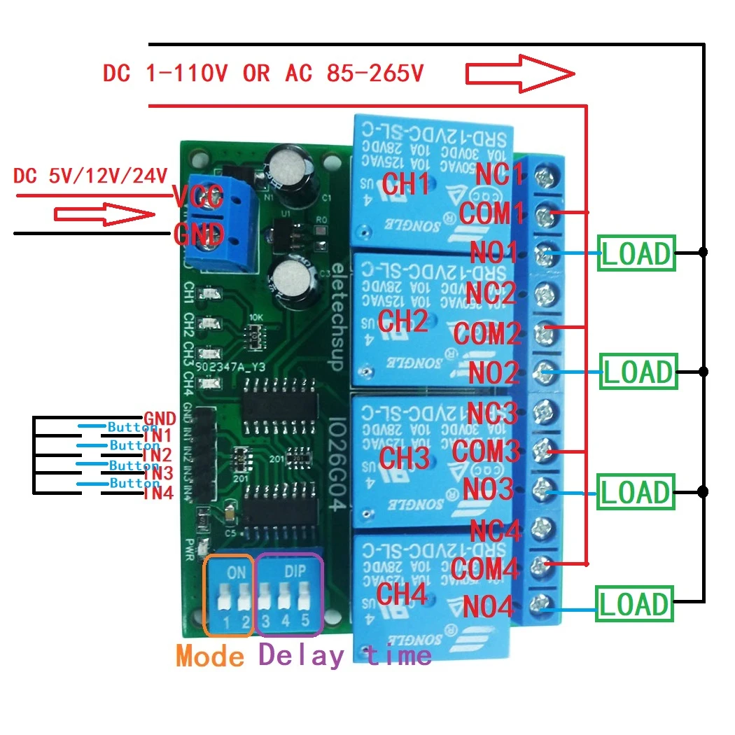
2 DC 1-100V OR AC 85-265V control circuit,Wiring diagram below. ''LOAD'' may be LED lights, fans, motors and other DC AC equipment
* Delivery Time.
We need 1-2 days to process your order before shipping.There are two shipping methoed. Fast Delivery: The delivery time for US, European countries the delivery will take 3-5 days.Slow Delivery: The delivery time for US, European countries the delivery will take 10-15 days.
* Tracking information.
After we ship package, customer receive automatic email with tracking details.
* Lost Package Policy.
If a package did not arrive in 4 weeks after the shipping date, then this package is treated as Lost. In this case a new package will be shipped to the customer provided we are able to give the same items as those purchased by the customer. If we are not able to provide the same items to substitute the lost ones we will either propose to the customer similar items or refund their cost as it will be mutually agree with the customer. If one or more items neither the same nor similar are available to be shipped, the customer can request to cancel the order entirely, thus the total cost of the order including shipping and handling cost will be fully refunded.


